
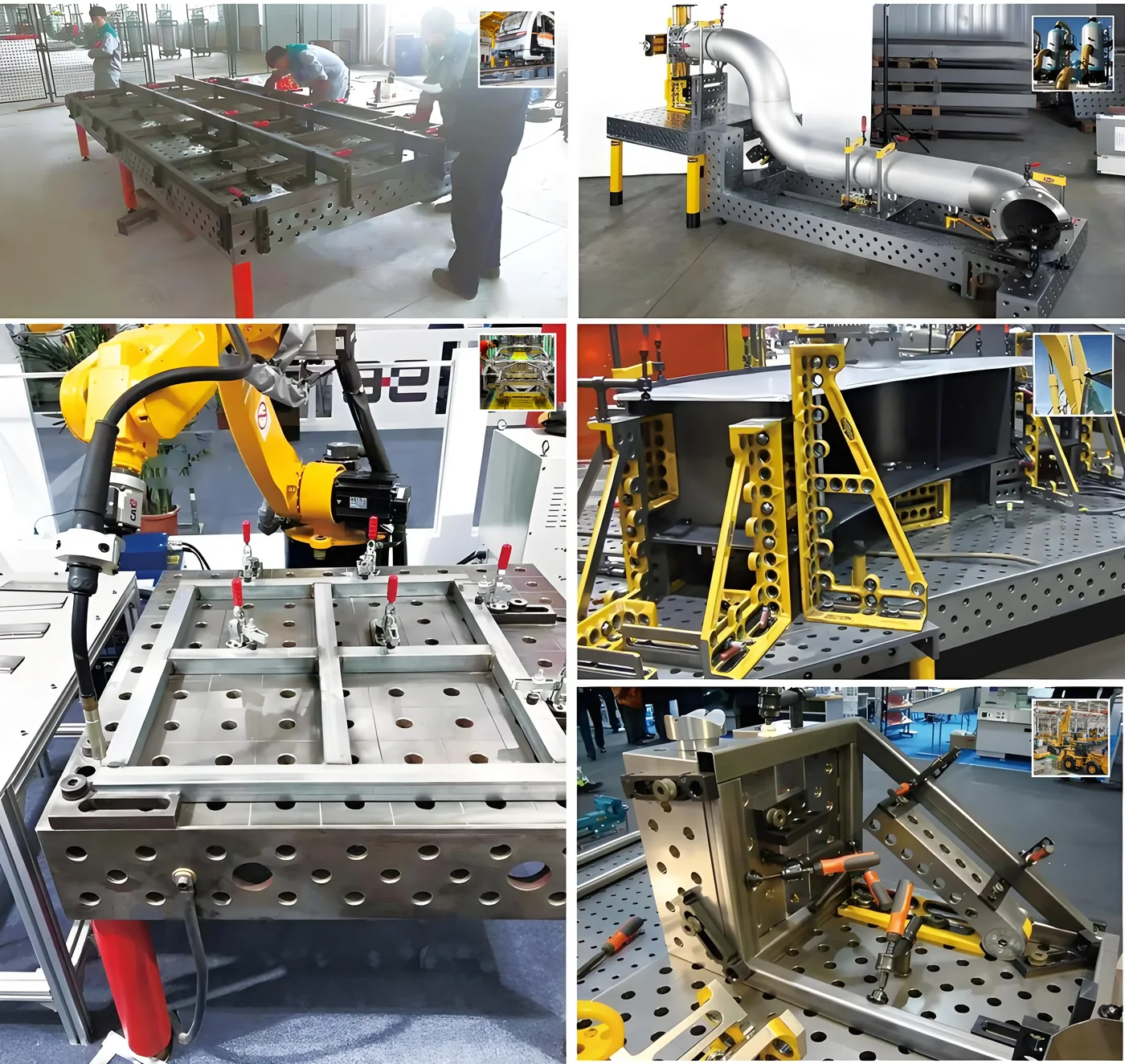
What the robot changes
A manual welder compensates: an operator adjusts tack order, grinds a high spot, holds a part a little differently when the fixture is loose. A robot does none of that. It repeats the path it was taught against the geometry in front of it, so whatever position error the fixture allows becomes part of every welded part, not an occasional defect.
The second change is access. The torch approaches the joint from angles the programmer chooses within the cell layout, and clamps, stops or supporting blocks that sit in those angles cause collisions or force awkward approaches. On a manual table a badly placed clamp is an annoyance; in a cell it is a crash or a program workaround that persists for the life of the part.
The third is changeover. When the cell runs several part families, the fixture must return each of them to a known position. Tooling that mounts back onto the same grid positions — rather than being re-squashed and re-measured each time — is what keeps changeover short and the taught programs valid.
A datum scheme the programmer can rely on
- Fix the primary datums in the fixture: the surfaces or edges that locate the part, held by stops and angle squares, not by hand judgement.
- Use the table grid as the coordinate frame. A 100 mm hole grid gives nominal positions that a program offset can reference without re-measuring each setup.
- Keep the same datum logic across part families on one table, so a new program starts from a known frame instead of a new one.
- Document the datum corners and the tooling positions for each part family, so changeover is a checklist rather than a re-invention.
- Treat the tabletop as the reference only if it is the reference. If the cell measures or programs from the table surface, the flatness grade becomes a specification item rather than a convenience.
Keep the top open: clamp off the seam
The torch needs corridor space to the joint, and the weld sequence needs the seam visible to the operator who sets up the part. Place clamps and stops below the joint line where possible, and use the table faces for what they are good at: on a five-face platform the side faces carry the same hole grid, so tall parts can be referenced vertically while the top stays clear for approach.
This is where the modular system earns its place in a cell. Fixtures for robot work are refined after the first articles are welded — a clamp moves, a stop gains a shim, a support is re-cut. Tooling that bolts to the grid can be repositioned between cycles; a welded dedicated fixture needs machining to change.
Choosing the hole system and table
One practical note on size: a cell magnifies the cost of reach. If the robot cannot reach a joint because the part sits far out on an oversized table, the fix is a fixture decision — pull the datum edge inboard — not a longer robot. Size the table from the clamp plan, then check reach against the cell layout with the fixture in place.
| Decision | What drives it |
|---|---|
| Hole system | Workpiece and clamping load, exactly as for manual work: D16 for compact parts and close tooling, D22 for mixed families, D28 for frames, bases and thick plate with heavier clamps |
| Table size | The largest workpiece envelope plus torch and clamp clearance, not just the part footprint |
| Platform height | Cell layout, part height and any positioner or handling interface; 100 or 200 mm bodies with custom heights |
| Flatness grade | Whether the table serves as the measuring or programming reference; 0.1 mm/m² standard, 0.05 and 0.02 mm/m² available |
| Surface treatment | Duty cycle: a nitrided surface suits a station where clamps and pins are used every shift |
Repeatability comes from the fixture, not the robot
The robot arm repeats its own path to a level the fixture rarely matches, which is why the workholding decides part-to-part consistency. What actually delivers repeatability on a modular table is unglamorous: pins seated fully in the same holes, clamps tightened the same way, stops that reference machined datums rather than a chalk line, and a first-article check after every changeover.
Wear works against this over time. Hole edges and clamp seats that wear from daily insertion loosen the very positions the program depends on, which is the argument for a hardened surface on a cell table that runs every shift.
What to send when enquiring
- The workpiece family: sizes, thicknesses and the tightest tolerance the assembly carries.
- A sketch of the weld access side — where the torch must reach and which areas must stay clear.
- The planned datum scheme, if it exists, or the drawing so one can be proposed.
- Preferred hole system, or the workpiece description for a recommendation.
- Whether the table is the measuring or programming reference, which sets the flatness grade.
- The accessory scope: starter kit for the first part family, or a full kit for several.