
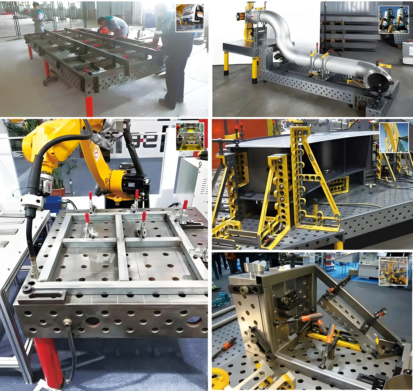
Repair work: the part arrives without a drawing
Production work arrives with a drawing, a datum scheme and a batch size. Repair work arrives on a trolley, sometimes in pieces, with a story instead of a specification. The bracket is bent, the housing is cracked, the frame has been modified twice before anyone now at the shop touched it. Whatever held the part when it was first made is long gone.
That changes what is being asked of the fixture. A production fixture answers one question, repeated: where does this part sit? A repair setup answers a different one every morning: where does this part sit today? The equipment under the work has to give up its geometry quickly, because none of it will be used in exactly the same place next week.
- Datums that can be set from the part itself, not from a drawing that no longer matches it
- Clamping positions that move to the damage, not to a fixed nest
- Access for welding from more than one side, because the repair does not care which face is convenient
- A setup that can be cleared in minutes when an urgent job jumps the queue
Why dedicated jigs struggle here
A dedicated jig is a machined answer to one part. That is its strength in production: the nests, locators and clamps are built for geometry that never changes, so the setup is fast and the result is identical every cycle. It is also why the same design fails in a repair bay. Dedicated fixtures need machining to change, and in repair work the geometry changes every job — there is nothing for the nest to repeat against.
The failure is not dramatic; it is a slow tax. The jig holds part of the work and the rest is propped on loose blocks. The clamp that fitted one repair presses on the damage of the next. Each job begins with a negotiation against equipment that was built for a different part, and the negotiation costs more time than the welding that follows.
Modular systems are the opposite bet: they are reconfigured with tooling rather than rebuilt with dedicated jigs. Instead of hardware shaped like one part, the bay carries a grid of known positions and a cabinet of elements that can be arranged to suit whatever arrives.
What modular tooling offers when every job is different
On a 3D table, the positions are fixed and everything above the surface moves. The holes sit at known spacings on the top and the four side faces, so a stop is not somewhere near the edge — it is at a named hole, and the same hole next week. That is what makes a repair setup describable, repeatable and clearable.
A modular table earns its place the first time a taller part, a boxed frame or a side-access weld arrives — the job a flat plate could not hold. In a repair bay those jobs are not exceptions; they are Tuesday. Five-face grids keep tooling positions available around the workpiece, so a long shaft can be referenced from the side face while its housing sits on the top, and clamps reach from whichever face the damage happens to be on.
Modular platforms also grow with the work. The first kit covers the common cases; supports, angle squares and extra clamps are added as the incoming jobs show what the bay actually handles. None of that growth requires the table to be modified — the same grid accepts every new element.
Deciding on the grid: hole system and spacing for mixed work
Repair bays see mixed work, so the grid should be chosen for the middle of the range, not for an extreme. D22 is the usual answer for a bay that sees brackets, small frames and machine parts of assorted sizes: large enough to take serious clamping, fine enough to position stops close to small geometry. Where heavy sections dominate — thick-wall housings, large frames — D28 takes the heavier tooling in the range.
Spacing decides how close the tooling can sit to the damage. A 50 mm grid puts stops and clamps nearer small features; 100 mm keeps more open surface for awkward shapes and fewer holes to keep clear. The two decisions are independent — spacing is available at 50 or 100 mm regardless of hole diameter — so a bay can have a fine grid without giving up clamp size.
One caution from workshop experience: in repair work the part is often not square, not clean and not complete. Locating elements set the datums and clamping holds what locating has set, and keeping that sequence matters more here than in production, because there is no jig to fall back on when the part moves.
- Hole system: D22 for mixed repair work; D28 where heavy sections dominate
- Spacing: 50 or 100 mm, chosen independently of the hole diameter
- Table sizes from 500 x 500 mm up to 4000 x 2000 mm; platform height 100 or 200 mm
- Tooling: kits matched to the hole system, extended as the repeating repairs become known
When a repair bay still needs a dedicated fixture
Modular does not make dedicated fixtures obsolete; it moves the line between them. When one repair recurs — the same housing family every month, the same frame repair agreed with a fleet operator — it has quietly become production, and production deserves a dedicated fixture. The honest test is repetition: the tenth time the same part is set up on the same stops in the same holes is the moment to consider machining a nest for it.
Until then, the modular table covers the bay, and it does so with a smaller commitment. A dedicated jig that loses its part becomes scrap; a modular setup that loses its job is cleared in minutes and the grid serves the next one. For a repair shop whose work arrives without a drawing, that difference is the whole argument.