
The name comes from where the grid goes
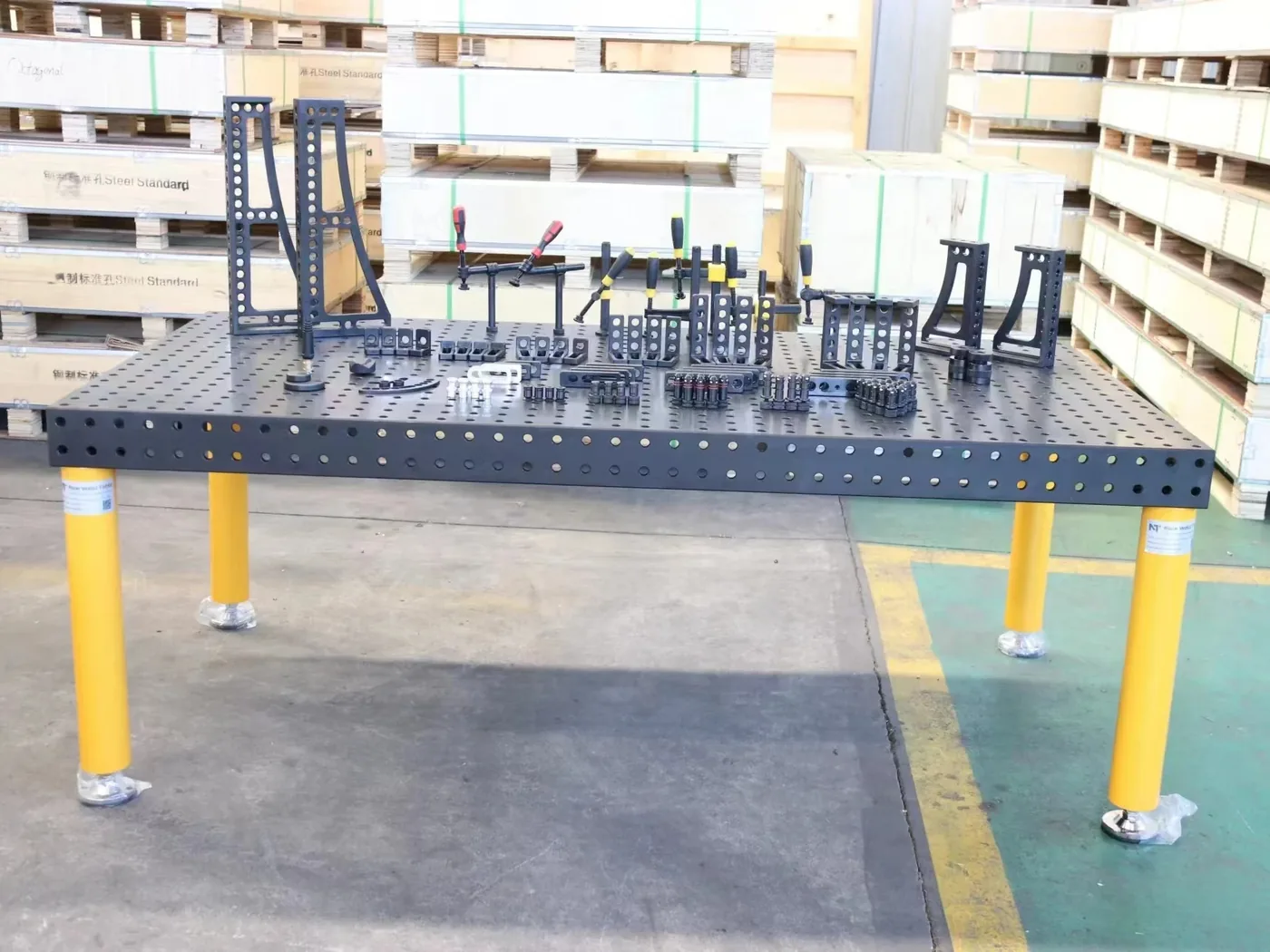
A plain welding plate gives you one working surface: a drilled or flat top. A 3D table machines the top face and the four side faces, and carries the same hole grid across all of them. The working surfaces are therefore at right angles to each other, and tooling can be mounted on any of them.
That is the whole idea in one sentence: the grid extends into three dimensions, so a part can be held against a vertical datum as well as down onto the tabletop. Stops, angle squares and clamps bolt into the holes at set positions, the assembly is located against them, and the setup can be taken apart and rebuilt for the next job without any welding of the tooling itself.
The hole system decides what fits
The holes come in standard diameters, and the choice defines the scale of every pin, clamp and stop the table will accept. D16, D22 and D28 are the common systems: D16 for compact parts and fine positioning, D22 for mixed fabrication where one table covers several job sizes, and D28 for large frames, bases and thick plate where holding force matters more than grid density.
The system you choose has to match across the table and the accessories. A D22 clamp will not seat in a D28 hole, so the hole system is the first decision and everything else follows it. If you are unsure, the workpiece size and weight are enough for a recommendation.
Accessories turn the grid into a fixture
A 3D table on its own is a flat, drilled surface — it cannot hold anything until tooling is added. The accessory range covers four working families plus maintenance: clamps that hold the part down or against a stop, locating elements that set the datums square, connecting pins and bolts that mount everything to the grid, and support blocks that carry overhanging or raised work.
Across those families the range runs to 188 individual SKUs, and the common families are also supplied as complete kits matched to the hole system. A starting kit covers clamping, squaring and connecting in matched sizes; single items are added later once the repeating operations are known.
Sizes, heights and flatness
- Table sizes from 500 x 500 mm up to 4000 x 2000 mm, built to the confirmed configuration.
- Platform body heights of 100 or 200 mm, with custom heights available.
- Flatness machined to 0.1 mm/m² as standard, 0.05 mm/m² precision and 0.02 mm/m² high precision where the table serves as a reference.
- Materials Q235, Q355, HT250 or HT300, with other materials available on request.
Who needs 3D — and who does not
If the work is flat, lightly clamped and always approached from above, a top-face surface does the same job and the side faces earn nothing. The 3D construction pays for itself when parts are tall or box-like and need a vertical datum, when seams must stay accessible on several sides, or when the station changes between jobs and a rebuildable fixture beats dedicated tooling.
A useful test is to sketch the largest workpiece and mark where clamps and stops would go. If everything happens on the top face, the answer is a simpler surface; if marks land on the sides, that is the 3D grid working.
How a table gets configured
A configuration starts with the workpiece: size, weight, process and the tolerance the assembly carries. From there the hole system, table size, platform height, flatness grade and surface treatment are settled and confirmed on a drawing before production. Delivery is typically around 10 days from confirmation.
You do not need to arrive with a complete specification. Describe the work and the recommendation comes back with the reasoning, so you can check it against your own requirements before committing.