
Start with the part on the table, not with the table on the floor
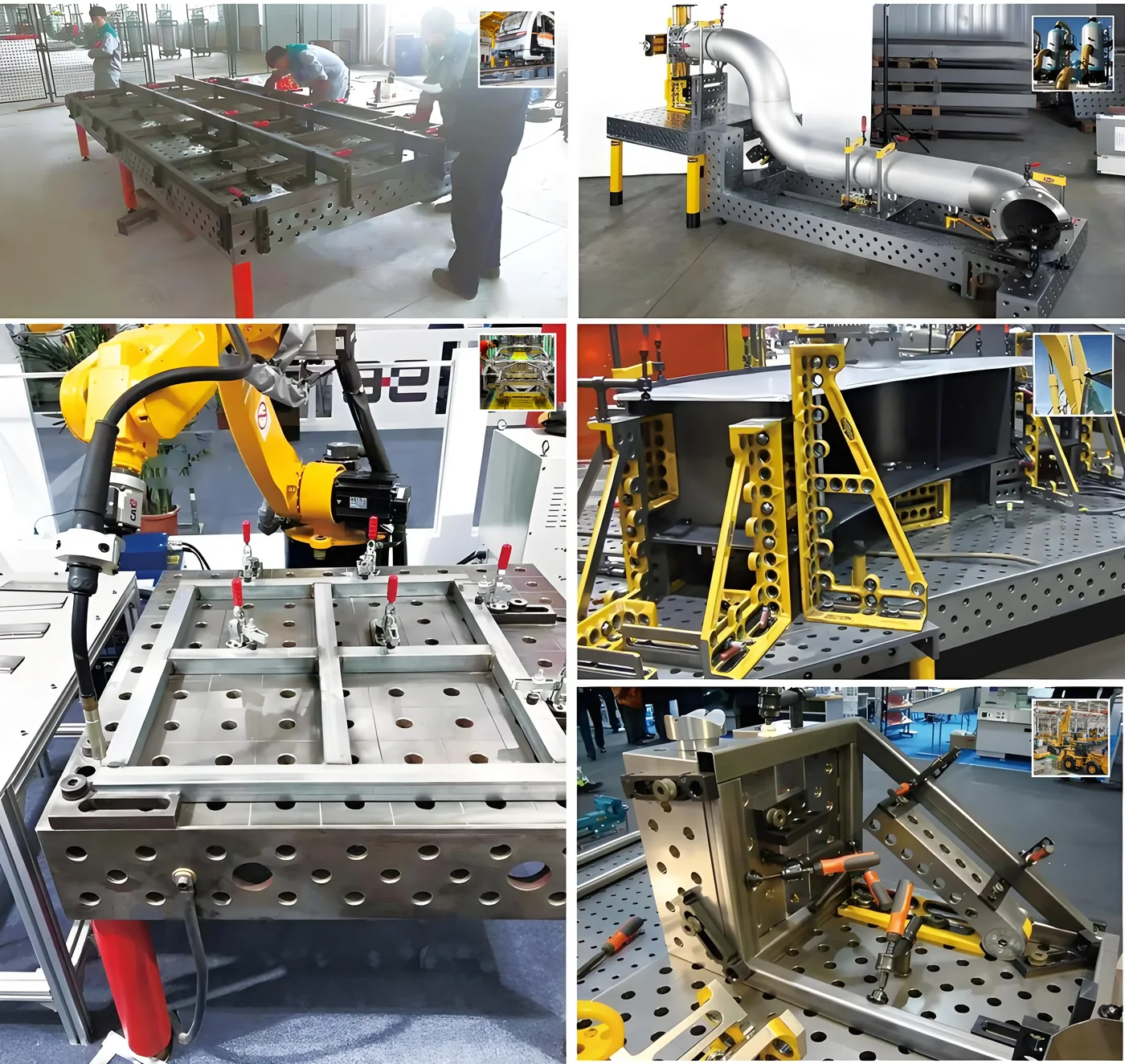
The common way to specify a welding table is to pick a size first and think about tooling later. The better way runs in the opposite direction: take the part you weld most, and mark where it must be held — the datum surfaces, the clamping points, the sides the torch approaches from.
Oversizing wastes reach and floor space. The table follows the clamp plan, not the room. A table that is larger than the fixture plan needs adds handling distance for the operator and machining cost per hole without holding any more of the work.
Locating first, clamping second: what each family does
The accessory range is organised into families: clamping, locating, connecting, support and maintenance. Two of them decide the fixture plan. Locating elements set the datums — angle squares, locating stops and stop-and-clamp combinations define where the part sits. Clamping holds what locating has set.
Getting that order right matters when you count hardware. Four to six clamping points is the typical hold for a frame, but that count only works when the locating is settled first: every clamp that also has to position the part is doing two jobs badly.
If a clamp is holding the part square, the locating is wrong or missing. Fix the datum setup and the clamping gets simpler and cheaper.
Sketching the clamp plan: datums, clamp points, access
The sketch does not need to be a CAD drawing. Mark on the part: which surface sets the height datum, which two faces set the square, where each clamp closes, and where the torch travels. Anything a clamp blocks is a weld the operator cannot reach.
From that sketch two numbers fall out directly. The first is the envelope of the part plus the margin around it for the clamps and stops themselves — that is the table size. The second is the distance between the closest clamp positions — that is what picks the hole system, because the tooling body has to fit between the holes it uses.
Reading the specification off the plan
Once the plan exists, the table specification reads off it. Size comes from the part envelope plus fixturing margin. Hole system comes from the tooling the clamp density requires. The accessory families you actually drew — locating, clamping, support — become the order list.
This is also the moment to check the side faces. A plan that holds the part in more than one plane needs mounting positions on the sides, which is exactly what distinguishes a 3D table from a plain drilled plate.
Quoting the platform and the tooling in one document
Accessories and the table should be quoted together so sizes match the hole system. A table ordered alone and tooling ordered later is where mismatches appear: a clamp that needs a hole spacing the table does not carry, or a stop set that assumes the wrong platform height.
One quotation built from the fixture plan keeps the hole system, the spacing and the accessory families consistent. It also makes the comparison between suppliers meaningful, because the tooling content is visible in the price rather than discovered at delivery.