
Why repeat work is the harder problem
The first part is a project. The tenth is a test. A one-off assembly can be carried by skill and attention: the welder finds a way to hold it, checks it, tacks it and moves on. Nothing is written down, because nothing will be asked of that setup again.
Repeat work asks a different question: not whether the part can be made, but whether the setup that made it can be rebuilt by someone else next month, without the original fitter at the table.
The usual failure is not a bad weld. It is a setup that lived in one person and left with them: blocks stacked to a height nobody measured, stops nudged so the part would drop in, a clamping order that worked but was never written down. Parts pass until an assembly downstream refuses them.
A hole grid changes that arithmetic, because it turns a setup into a set of addresses.
Known positions: what the grid actually gives you
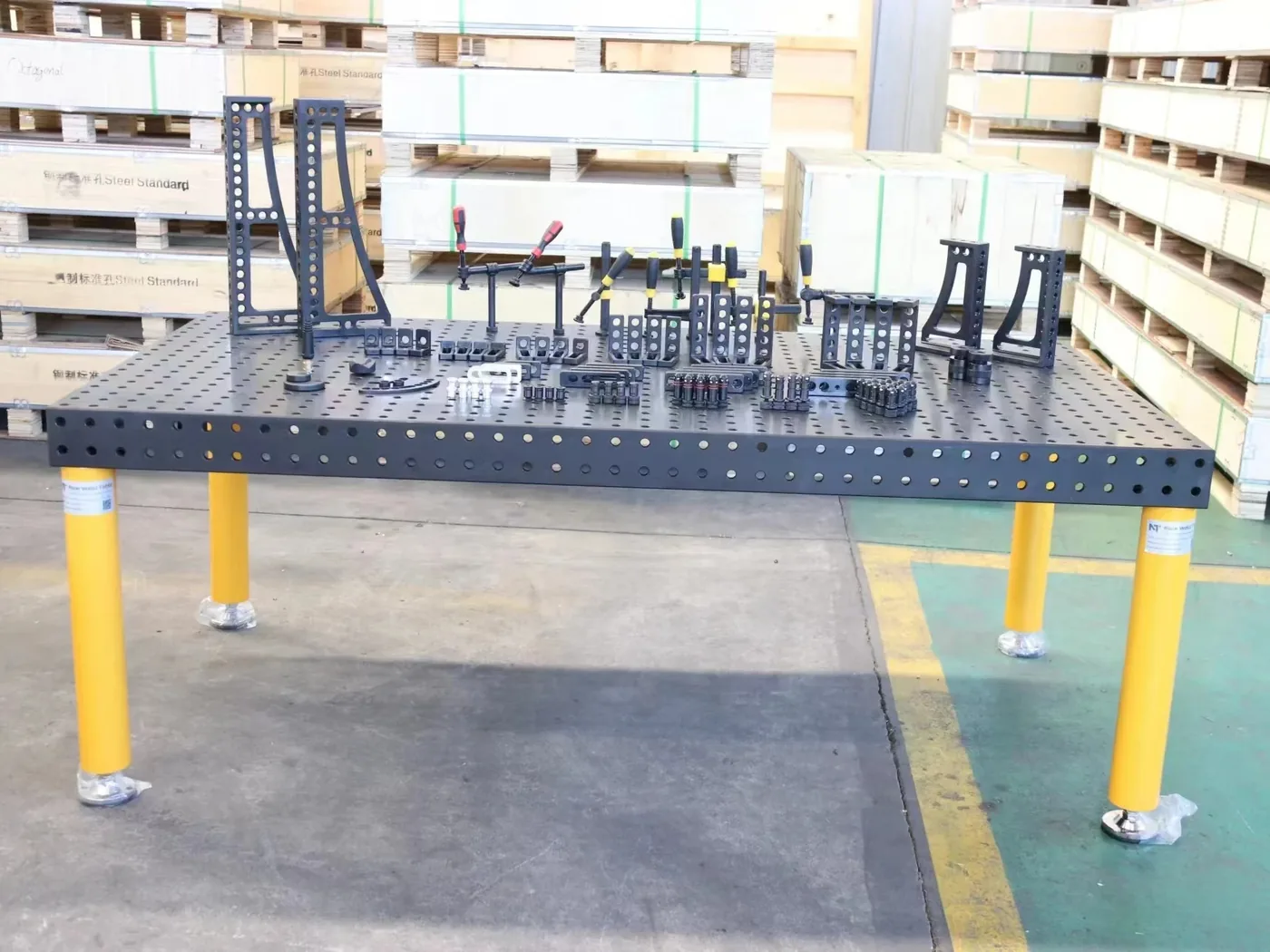
The useful property of a modular table is not the holes but the fact that every hole has an address. Holes sit at known positions at 50 or 100 mm spacing, so a stop is not somewhere near the left edge — it is in a specific hole, and the same hole next week.
That turns a setup into a description rather than a memory: which faces the part was located from, which holes carried the stops, which elements sat in them, and in what order the clamps came down. Anyone who can read the list can rebuild the setup.
Keep the roles apart. Locating elements set the datums; clamping holds what locating has set. The locating family covers angle squares, locating stops and stop-and-clamp combinations: a square sets an axis, a stop sets a position along it. A part that comes out twisted usually had a clamp pulling it into place instead.
Spacing decides how precisely those addresses can be placed. A 50 mm grid puts stops closer to small features; 100 mm leaves more open surface. Either is available with any hole diameter, so a fine grid does not force a smaller clamp.
Recording a setup so it can be rebuilt
A setup card does not need to be a document. One page, five lines and a photograph is enough, provided the five lines are the right ones. The test is simple: hand it to someone who has never run the job and see whether the part lands in the same place.
| Line on the card | What it records | What it prevents |
|---|---|---|
| Datum faces | Which part faces the stops were set against | A setup squared from the wrong edge |
| Hole addresses | The holes used for stops and clamps | A stop placed near the right spot, not in it |
| Element list | Which square, stop or clamp sat in each hole | A rebuild that looks right and holds differently |
| Check before tack | The measurement taken once located | Clamping a part that was never square |
| Overhead photo | The finished setup, shot square to the table | The version of the setup people remember |
Keeping the card where the tooling is
The photograph matters more than it looks. A card written from memory describes the setup as it was meant to be; a photograph records it as it was. Together the five lines cover what a drawing of the part cannot: how this shop chose to hold it.
Keep the cards with the tooling and name them by part or operation, not by date. A card is only useful if the next person can find it, and cards kept beside the elements they describe get corrected when an element is replaced.
The check that catches a drifted setup: does the pin seat
Before trusting a card, check the table. A pin that seats fully is the practical test of a hole position: if it drops through the element into the hole without effort, the address is where the card says it is. If it binds, something has moved, and the setup about to be built there is suspect.
The test reports on the setup rather than the part. Measuring the finished part says the result was wrong; it does not say where the error entered. The pin test comes before any welding and separates three faults that otherwise look identical: a damaged hole, a worn element, a stop never seated.
Run it on the holes the card names rather than a convenient sample. Those addresses matter, and they are exactly the holes that collect spatter, grit and the small dents left by clamping in one place for years. A pass before the first part also clears the hole.
When a repeat setup still needs a dedicated stop
Modular tooling handles most repeats, but not equally. When the same setup runs for months unchanged, the card becomes the weak link: a fixed stop that stays in place removes the rebuild step, and with it the chance of a rebuild done slightly differently. That is when a dedicated element earns its place.
Batch orders extend the logic across tables. Platforms are produced in batches against one confirmed drawing, so the hole grid repeats from table to table, and every table in a batch follows the same drawing, hole system and flatness grade. A card written for the first table transfers to the second, which is the practical reason to settle the hole system once when more than one table is planned.
The habit that holds it together is unglamorous: write the card, photograph the setup, check the pin, put the elements back where they came from. None of it is difficult; all of it is easy to skip on a busy day.