
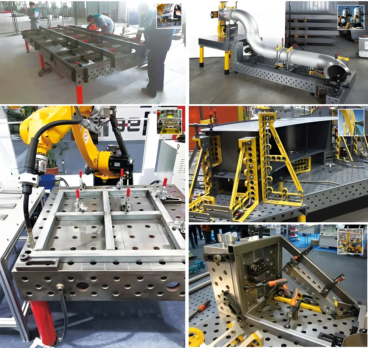
The table is the centre; the layout is everything around it
Two tables with identical specifications can perform completely differently depending on where they stand. A table pushed against a wall loses the side-face access that justified a five-face platform. A table placed under a crane gains handling convenience but may lose headroom for tall fixtures. The layout decides whether the specification you paid for is actually usable.
So the planning unit is not the table — it is the station: the table, its support, the operator positions, the part flow in and out, and the services that feed the process.
Access first: which sides must stay open
Whether operators need access from all four sides is a question that changes the support design, which is why it appears on the RFQ checklist. Four-side access suits large fabrications approached from any direction and makes the full five-face grid usable. Two-side access against a wall suits compact work and saves floor space — but it should be a decision, not an accident of where the table landed.
Mark the access sides on the sketch, and keep the sides with the heaviest tooling open. Side-face clamping needs standing room along those faces, not just a few centimetres.
Handling: how parts arrive and leave
- Crane or hoist placement affects access and handling clearances — confirm the hook path over the table working area.
- Trolleys and positioners need approach routes that do not cross the operator position.
- The largest workpiece defines the turning and approach space, not the table footprint.
- State the handling method in the RFQ so the support design is made around it.
Height and reach: the operator envelope
The working height is a chain from the floor: support, platform body, fixture, part. Around that chain, the operator needs standing room and torch access, and nothing above the working feature — a crane rail, a shelf, a duct — that forces a bent posture. The size guide walks through the calculation from operator elbow height.
Reach also grows with table width. A wide table doubles the fixture area but moves its centre out of comfortable reach; access from both long sides recovers it. This is the same reasoning as the size decision, applied to the floor plan.
Fixed or mobile within the layout
A fixed station on levelling feet is levelled once around its process and stays put — the reference condition for precision work and the anchor for services routing. A mobile base lets the table move between bays or aside for access, at the cost of stability under heavy clamping. In a layout sketch, mobile tables need a destination for every position they may occupy — including floor condition and level at each.
Services and the items to confirm before installation
Power, shielding gas and fume extraction all route around the station, and each has a preferred side depending on the process and the building. These are qualitative planning items: mark where services enter, keep them clear of the access sides you marked, and confirm the routing with the installer before the support frames are fixed in place.
The layout sketch checklist
One sketch with those six items is enough for a supplier to design the support and confirm the configuration — and it prevents the two classic regrets: a table that cannot be reached from the side it needed, and a crane that cannot reach the work.
- Table footprint plus the access sides marked as open.
- Part flow: arrival route, loading method, exit route.
- Handling equipment and its clearances.
- Operator standing positions on both long sides where applicable.
- Service entry points for power, gas and extraction.
- Final position, floor condition and levelling plan.